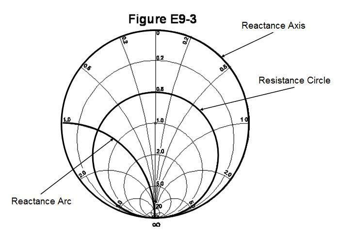
Smith Chart

A Smith chart is shown above and is a graphical tool used for calculating impedance along transmission lines and SWR values for transmission line to antenna matching. The chart consists of circles of constant values of resistance, (resistance circles), and arcs of constant values of reactance, (reactance arcs). The outside circle is labeled with a value for each reactance arc and is called the reactance axis. The vertical line that splits the Smith chart is where each resistance circle is labeled with a value and is called the resistance axis.
Questions
Which of the following can be calculated using a Smith chart?
A. Impedance along transmission lines
B. Radiation resistance
C. Antenna radiation pattern
D. Radio propagation
What type of coordinate system is used in a Smith chart?
A. Voltage circles and current arcs
B. Resistance circles and reactance arcs
C. Voltage lines and current chords
D. Resistance lines and reactance chords
Which of the following is often determined using a Smith chart?
A. Beam headings and radiation patterns
B. Satellite azimuth and elevation bearings
C. Impedance and SWR values in transmission lines
D. Trigonometric functions
What are the two families of circles and arcs that make up a Smith chart?
A. Resistance and voltage
B. Reactance and voltage
C. Resistance and reactance
D. Voltage and impedance
What type of chart is shown in Figure E9-3?
A. Smith chart
B. Free-space radiation directivity chart
C. Elevation angle radiation pattern chart
D. Azimuth angle radiation pattern chart
On the Smith chart shown in Figure E9-3, what is the name for the large outer circle on which the reactance arcs terminate?
A. Prime axis
B. Reactance axis
C. Impedance axis
D. Polar axis
On the Smith chart shown in Figure E9-3, what is the only straight line shown?
A. The reactance axis
B. The current axis
C. The voltage axis
D. The resistance axis